B. Kainka
 The Arduino-Inside Measurement Lab
Elektor 2024
https://www.elektor.com/products/the-arduino-inside-measurement-lab
A well-equipped
electronics lab is full of power supplies, measuring devices, test
equipment and signal generators. In addition, there are tools,
components and the many assemblies and projects that you are currently
working on. It can get crowded in the lab. Wouldn't it be better to
have one compact device for almost all tasks? All in one, small and
versatile, and also inexpensive and easy to procure.
After several attempts with other systems the choice fell on the
Arduino Nano. On this basis, a PC interface as versatile as possible
for measure-ment and control is to be developed. It simply hangs on a
USB cable and, depending on the software, forms the measuring head of a
digital voltmeter or PC oscilloscope, a signal generator, an adjustable
voltage source, a frequency counter, an ohmmeter a capacitance meter, a
charac-teristic curve recorder and much more.
The circuits and methods collected here are not only relevant for
exactly these tasks in the electronics laboratory, but many details can
also be used in completely different contexts. Often one encounters
complex tasks in the field of measurement technology during development
work with microcontrollers. In many cases, the methods from this book
can then be used. You have a starting point and can develop the
software in the desired direction.
Stay creative!
Burkhard Kainka
Software download: ArduinoMSR.zip
More information: www.elektronik-labor.de/AVR/ArduinoMSR.html
CONTENTS
1 Preparations 1
1.1 Choice of controller 1
1.2 The Arduino Nano 3
1.3 Voltage supply 5
2 Preliminary tests 8
2.1 Port outputs 8
2.2 Analog inputs and outputs 12
2.3 The serial plotter 15
2.4 PWM signal generator 18
2.5 A sawtooth generator 20
2.6 Direct digital synthesis 23
3 GCC programming 27
3.1 Fast port outputs 27
3.2 PWM output 28
3.3 Timer interrupt 32
3.4 Fast sine wave generator 34
3.5 AD buffering 41
4 The MSR Laboratory 49
4.1 Dual-channel DDS generator 50
4.2 Binary serial transmission 52
4.3 Frequency setting 55
4.4 Deflection times and dual-channel operation 59
4.5 Triggering 64
4.6 DC voltage output 66
5 Additional inputs and outputs 69
5.1 Phase adjustment of the DDS 70
5.2 Signal generator up to 8 MHz 71
5.3 Frequency measurement 75
5.4 Additional analog inputs 80
5.5 Capacitance measurement from 1 pF 82
5.6 Resistance measurement up to 1 MΩ 85
5.7 Resistance measurement from 1Ω 88
6 Measurements and experiments 90
6.1 Subsampling 90
6.2 Investigation at higher frequencies 93
6.3 Measurement on a synchronous signal 95
6.4 Frequency response of a low-pass filter 97
6.5 An LC low pass 101
6.6 LC resonance 104
6.7 Transistor test circuit 107
7 Firmware extensions 112
7.1 Alternative DDS functions 112
7.2 Reduced amplitude 113
7.3 Triangle and sawtooth 114
7.4 XY representation 117
7.5 Frequency sweep 121
7.6 Ramp function 124
7.7 Measurement of characteristic curves 128
8 Application examples 132
8.1 The emitter follower 132
8.2 Emitter follower as impedance converter 133
8.3 Sallen key filter 135
8.4 Beat generator 137
8.5 Operational amplifier 139
8.6 Voltage doubling 142
8.7 All-pass filter 144
8.8 Bandpass filter 147
Appendix 150
List of components used 150
FAQ
It is unclear to me how the various components are to be combined: I
can start: Terminal.exe, MSR.exe, but it is unclear to me how the
various parts work together, the DDS1 and 2 etc
In the beginning I only use the Arduino software for programming DDS1,
DDS2 and so on and for the Serial Monitor and the Serial Potter.
Later, e.g. page 38, I use Terminal.exe instead of the Serial Monitor
in order so to see the bytes sent. In this case the Serial Monitor must
be inactive to leave the COM free.
Chapter 5 shows the step by step development of the firmware and the VB6program MSR.exe. The end result is MSR2.exe.
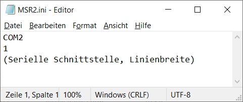
If you want to use the final software MSR2.exe for all the experiments
in chapter 6 to 8 you must flash NanoMSR2.ino into the Nano. Also you
must edit MSR2.ini to write the COM number like COM2 or whatever your
Arduino uses. Default is COM2.
See also https://www.elektronik-labor.de/AVR/ArduinoMSR.html
When you start MSR2.exe and see an error message “COM error”, one of the following things may have occurred:
-
The COM in MSR2.ini is wrong.
-
The Arduino is not on USB.
-
Some other software is still active, occupying the COM.